

Filtration without additives
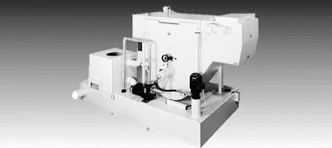
Drum filter HTV95V - HTF230V
Continuous cleaning of contaminated cooling lubricants as they occur when using machine tools. Recommended for use for high flow rates as the flow rate is increased three to four times with the same filter area and without filter medium consumption compared to a gravity filter.
The contaminated cooling lubricant flows from the machine tool via an inlet distributor into the contaminant chamber of the filter. Inside the contaminant chamber is a filter drum covered with a seamless stainless steel filter fabric. The pressure difference Δp generated between the contaminant and inner space of the filter drum by means of a vacuum suction pump causes the medium to be sucked into the inner space of the filter drum, whereby chip and dirt particles are filtered out through the filter fabric. The filter cake forming on the filter fabric surface generates an increasing partial vacuum in the inner space. When a preset value is reached, a contact pressure gauge initiates regeneration. The filter drum starts to rotate and the filter cake is lifted off the filter drum by a stationary scraper and removed by scraper plates connected to endless chains and driven by a geared motor. The scraper plates pick up the dirt on the tank bottom and transport it over an incline to the discharge edge. As the discharge edge is located above the liquid level, the contaminant discharge is simultaneously dewatered to enable easy disposal. A stationary nozzle assembly is installed inside the drum interior, which is supplied externally with clean medium. The rotation of the filter drum causes the filter fabric to be flushed free over the entire surface from the inside to the outside; this prevents clogging of the filter fabric.
-
Sturdy steel plate housing
-
Interchangeable scraper plates
-
Bush conveyor chain with hardened rollers
-
Central support of the filter drum
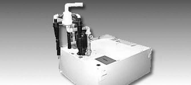
Hydrocyclone ZY55-1-ZY55-4
Hydrocyclone cooling lubricant cleaning plants operate wherever heavy dirt particles have to be separated from low-viscosity liquids. For example on machine tools (especially grinding machines). Also on machining centres, transfer lines or parts cleaning plants.
The liquid to be cleaned flows into the cylindrical part of the hydrocyclone via the inlet spiral at a pressure of 2.2 bar. The tangential arrangement of the inlet and high flow velocity gives rise to the formation of a primary vortex that rotates at high speed which increases continuously with the decreasing diameter of the cone housing. As a result of the high rotational speed, considerable centrifugal forces act on the dirt particles which are forced against the walls of the cyclone and discharged with a small quantity of water through the underflow nozzle. The flow resistance increases due to the narrowing cross-section in the cone housing. This reverses the direction of rotation of the primary vortex in the lower area of the cyclone. Rotating in the same direction, the resulting secondary vortex moves upwards through the immersion tube into the clean water chamber. There is an air core within the secondary vortex which aerates the coolant and so acts as an anti-putrefactive agent.
-
Centrifugal separator
-
Wear-resistant plastic housing
-
Easily replaceable components